

According to the shape of the flexible wheel, harmonic gear reducers can be divided into cup shaped and hollow shaped. According to the length of the flexible wheel, each type is further divided into two types, i.e., standard and dwarf. In addition, the same model includes several transmission ratios.
Flexible wheel shape: it is divided into two types: cup shape and hollow shape. The cup shaped flexible wheel is represented by the capital letter C, and the hollow shaped flexible wheel is represented by the capital letter H
Flexible wheel length: it is divided into two types: standard and dwarf. Standard flexible wheel is represented by the capital letter S, while short flexible wheel is represented by the capital letter D
Torque: it is divided into standard and high torque, high torque is represented by G, otherwise it is the standard type
Specification codes (6): they are divided into 14, 17, 20, 25, 32 and 40, corresponding to harmonic gear pitch diameter 35.6, 43.2, 50.8, 63.5, 81.3, and 101.6, respectively
The principle of harmonic gear transmission was first proposed by engineer А.И.Москвитин in 1947 and invented by American engineer C.W.Musser in 1955.
A new transmission method that uses the elastic deformation of flexible working components to transmit motion or power has overturned the mode of mechanical transmission using rigid components, thereby obtaining a series of special functions that are difficult to achieve with other transmissions. The deformation process of the intermediate flexible component is basically a symmetrical harmonic of a cosine, hence the name.
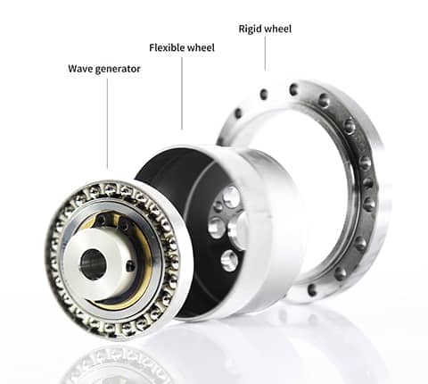
Rigid wheel: a rigid circular component with gears engraved on the inner circumference, which have 2 more teeth than the flexible wheel and are usually fixed on the casing.
Flexible wheel: a thin-walled cup shaped metal elastic component with gears engraved on the outer circumference of the opening. The bottom of the flexible wheel is called the diaphragm and is usually installed on the output shaft.
Wave generator: it is a component that assembles a thin-walled ball bearing on the outer circumference of an elliptical cam. The inner wheel of the bearing is fixed on the cam, and the outer wheel can undergo elastic deformation through the ball, usually installed on the input shaft.
The reduction principle of harmonic gear transmission utilizes the relative motion of the flexible wheel, rigid wheel and wave generator (mainly the controllable elastic deformation of the flexible wheel) to achieve motion and power transmission. The elliptical cam inside the wave generator rotates inside the flexible wheel, causing deformation of the flexible wheel. When the flexible gear teeth and rigid gear teeth at both ends of the elliptical long shaft of the wave generator enter meshing, the flexible gear teeth at both ends of the short shaft detach from the rigid gear teeth. When the teeth between the long and short axes of the wave generator gradually enter a semi-meshing state along different sections of the circumference of the flexible and rigid wheels, it is called mesh in. When it is in a gradual withdrawal state, it is called mesh out. When the wave generator rotates continuously, the flexible wheel continuously undergoes deformation, causing the teeth of the two wheels to continuously change their original working states during mesh in, meshing, mesh out, and detachment, resulting in staggered tooth motion, achieving the transmission of motion from the active wave generator to the flexible wheel.
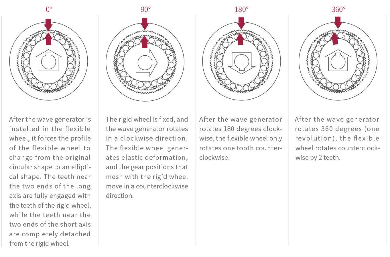
0 °: after the wave generator is installed in the flexible wheel, it forces the profile of the flexible wheel to change from the original circular shape to an elliptical shape. The teeth near the two ends of the long axis are fully engaged with the teeth of the rigid wheel, while the teeth near the two ends of the short axis are completely detached from the rigid wheel;
90 °: the rigid wheel is fixed, and the wave generator rotates in a clockwise direction. The flexible wheel generates elastic deformation, and the gear positions that mesh with the rigid wheel move in a counterclockwise direction
180 °: after the wave generator rotates 180 degrees clockwise, the flexible wheel only rotates one tooth counterclockwise
360 °: after the wave generator rotates 360 degrees (one revolution), the flexible wheel rotates counterclockwise by 2 teeth
Dedicated person coordination/personalized customization: for harmonic reducers customized by customers, Boyin will arrange dedicated person coordination and lock in customer needs through one-on-one efficient communication to ensure product quality and delivery time.
R&D advantages: Boyin R&D team focuses on theoretical calculations and accumulates massive test data through finite element analysis, combined with detection systems, to optimize tooth shape and structure, ensuring that the various features of the product are more stable and reliable.
Pre-research and development: Boyin has shifted its research and development focus to robot application scenarios, designing adaptive application solutions based on factors such as job types and working conditions, and integrating demand factors.
Forward looking research and development: Boyin uses more sophisticated and intelligent harmonic reducers to help upgrade robots and lead industry development.
Digital R&D: Boyin uses a digital R&D system to establish product optimization models to achieve precise calculations, provide customers with efficient customization solutions, and promote robot iteration and upgrading.
Design verification: Boyin designs the tooth shape and overall components of the harmonic reducer in the early stage, and predicts the performance, motion range, collision detection, peak load, and calculated input load of the mechanical system through finite element simulation analysis. Afterwards, the product is processed and formed. In the later stage, Boyin carries out a series of tests, including break-in testing, load testing, fatigue testing, and other long-term verifications, to ensure that the product meets strict data requirements. Otherwise, it will need to return to the early design stage.
Equipment advantages: for the processing of the three major components of the harmonic reducer (rigid wheel, flexible wheel and wave generator), Boyin has introduced world-class high-precision and high-efficiency imported equipment, providing sufficient guarantees for product accuracy and stability, while greatly increasing production capacity.
Technological advantages: the flexible wheel is a key component of the harmonic reducer. Boyin improves the mechanical properties of the flexible wheel through multiple heat treatment processes and special surface treatment during the manufacturing process, thereby ensuring the reliability and stability of the product and greatly improving the service life of the flexible wheel.
Process controllability: Boyin implements full process monitoring of incoming materials, processing, assembly, testing, etc., including material composition analysis before incoming materials, metallographic testing, various data detection during processing, tooth shape analysis during assembly, assembly testing, and load, fatigue, back clearance and transmission accuracy test, etc., in order to implement strict monitoring in the production process.
Multi-dimensional testing: the harmonic reducer has undergone a series of rigorous testing before leaving the factory, including three-dimensional dimension measurement, gear detector tooth shape analysis, the tests of back clearance, torque, transmission efficiency, etc. Through this method, Boyin has achieved the five tests and three major performance diagnoses for the flexible wheel, ensuring that the flexible wheel is strong and powerful, and the harmonic wave is strong, as well as ensuring that the quality of the delivered harmonic reducer is controllable (as shown in the picture of CNAS10 test on the right )